9 Electricity and Electrical Circuits
Learning Objectives
After successful completion of this section, you will be able to demonstrate competency in the following areas:
- Define: static electricity (CLO2)(CLO3)
- Determine the type of electric charge present (CLO2)(CLO3)(CLO4)
- State units of charge and electric force in SI units (CLO2)(CLO5)
- Explain various electrostatic interactions (CLO2)(CLO3)
- Define: electrical force, and electric field (CLO2)
- State Coulomb’s law (CLO1)(CLO2)
- Discuss the relationships between the variables in Coulomb’s Law equation (CLO2)(CLO3)(CLO5)
- Describe interactions between charges and electric fields (CLO2)(CLO3)
- Use Coulomb’s Law to calculate electric force (CLO5)
- Compare the Coulomb force to the gravitational force (CLO2)(CLO3)(CLO5)
- Define electric current, electric resistance, and voltage (CLO2)(CLO3)
- State Ohm’s law (CLO1)
- Use the correct units of current, voltage, and resistance in the metric systems (CLO5)
- Explain the relationships between the variables in the Ohm’s law formula (CLO2)(CLO3)
- Use Ohm’s law to solve simple circuit problems (CLO5)
- Determine the electric resistance, voltage, electric current, and power in a circuit (CLO2)(CLO3)(CLO5)
- Discuss the relationship between energy, power, voltage, current, and resistance in a circuit (CLO2)(CLO3)
- Describe and differentiate between parallel and series electrical circuits (CLO2)(CLO3)
- Determine the equivalent resistance for series and parallel combinations of resistors (CLO2)(CLO5)
Introduction to Electricity
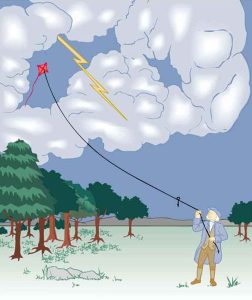
The image of American politician and scientist Benjamin Franklin (1706–1790) flying a kite in a thunderstorm is familiar to many schoolchildren. (See Figure 9.2) In this experiment, Franklin demonstrated a connection between lightning and static electricity. Sparks were drawn from a key hung on a kite string during an electrical storm. These sparks were like those produced by static electricity, such as the spark that jumps from your finger to a metal doorknob after you walk across a wool carpet. What Franklin demonstrated in his dangerous experiment was a connection between phenomena on two different scales: one the grand power of an electrical storm, the other an effect of more human proportions. Connections like this one reveal the underlying unity of the laws of nature, an aspect we humans find particularly appealing.
Static Electricity and Conservation of Charge

What makes plastic wrap cling? Static electricity. Not only are applications of static electricity common these days, its existence has been known since ancient times. The first record of its effects dates to ancient Greeks who noted more than 500 years B.C. that polishing amber temporarily enabled it to attract bits of straw (see Figure 9.3). The very word electric derives from the Greek word for amber (electron).
Many of the characteristics of static electricity can be explored by rubbing things together. Rubbing creates the spark you get from walking across a wool carpet, for example. Static cling generated in a clothes dryer and the attraction of straw to recently polished amber also result from rubbing. Similarly, lightning results from air movements under certain weather conditions. You can also rub a balloon on your hair, and the static electricity created can then make the balloon cling to a wall. We also have to be cautious of static electricity, especially in dry climates. When we pump gasoline, we are warned to discharge ourselves (after sliding across the seat) on a metal surface before grabbing the gas nozzle. Attendants in hospital operating rooms must wear booties with a conductive strip of aluminum foil on the bottoms to avoid creating sparks which may ignite flammable anesthesia gases combined with the oxygen being used.
Some of the most basic characteristics of static electricity include:
- The effects of static electricity are explained by a physical quantity not previously introduced, called electric charge.
- There are only two types of charge, one called positive and the other called negative.
- Like charges repel, whereas unlike charges attract.
- The force between charges decreases with distance.
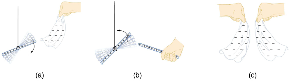
How do we know there are two types of electric charge? When various materials are rubbed together in controlled ways, certain combinations of materials always produce one type of charge on one material and the opposite type on the other. By convention, we call one type of charge “positive”, and the other type “negative.” For example, when glass is rubbed with silk, the glass becomes positively charged and the silk negatively charged. Since the glass and silk have opposite charges, they attract one another like clothes that have rubbed together in a dryer. Two glass rods rubbed with silk in this manner will repel one another, since each rod has positive charge on it. Similarly, two silk cloths so rubbed will repel, since both cloths have negative charge. Figure 9.4 shows how these simple materials can be used to explore the nature of the force between charges.
More sophisticated questions arise. Where do these charges come from? Can you create or destroy charge? Is there a smallest unit of charge? Exactly how does the force depend on the amount of charge and the distance between charges? Such questions obviously occurred to Benjamin Franklin and other early researchers, and they interest us even today.
Charge Carried By Electrons and Protons
Franklin wrote in his letters and books that he could see the effects of electric charge but did not understand what caused the phenomenon. Today we have the advantage of knowing that normal matter is made of atoms, and that atoms contain positive and negative charges, usually in equal amounts.
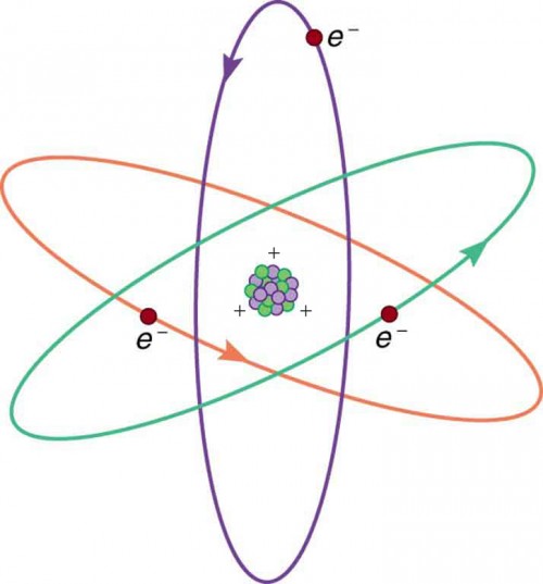
Figure 9.5 shows a simple model of an atom with negative electrons orbiting its positive nucleus. The nucleus is positive due to the presence of positively charged protons. Nearly all charge in nature is due to electrons and protons, which are two of the three building blocks of most matter. (The third is the neutron, which is neutral, carrying no charge.) Other charge-carrying particles are observed in cosmic rays and nuclear decay, and are created in particle accelerators. All but the electron and proton survive only a short time and are quite rare by comparison.
The charges of electrons and protons are identical in magnitude but opposite in sign. Furthermore, all charged objects in nature are integral multiples of this basic quantity of charge, meaning that all charges are made of combinations of a basic unit of charge. Usually, charges are formed by combinations of electrons and protons. The magnitude of this basic charge is
∣qe∣=1.60×10⁻¹⁹C.
The symbol q is commonly used for charge and the subscript e indicates the charge of a single electron (or proton).
The SI unit of charge is the coulomb (C). The number of protons needed to make a charge of 1.00 C is
1.00 C × (1proton/1.60×10−19C)=6.25×1018protons.
Similarly, 6.25×10¹⁸ electrons have a combined charge of −1.00 coulomb. Just as there is a smallest bit of an element (an atom), there is a smallest bit of charge. There is no directly observed charge smaller than ∣qe∣, ), and all observed charges are integral multiples of ∣qe∣ .
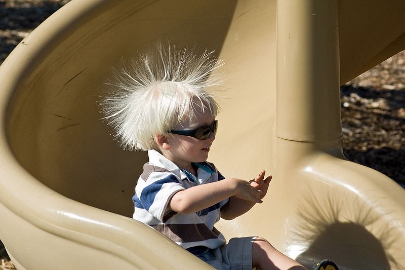
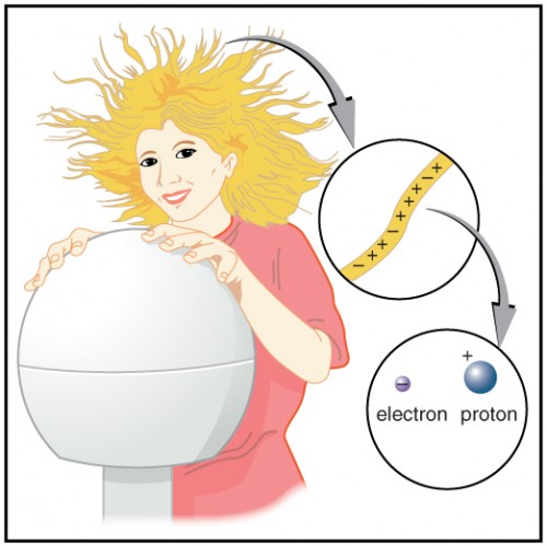
Figure 9.6 shows a person touching a Van de Graaff generator and receiving excess positive charge. The expanded view of a hair shows the existence of both types of charges but an excess of positive. The repulsion of these positive like charges causes the strands of hair to repel other strands of hair and to stand up. The further blowup shows an artist’s conception of an electron and a proton perhaps found in an atom in a strand of hair.
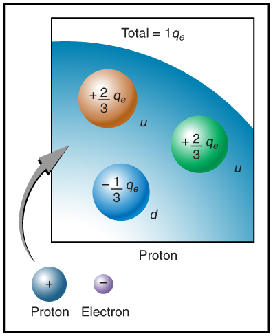
The electron seems to have no substructure; in contrast, when the substructure of protons is explored by scattering extremely energetic electrons from them, it appears that there are point-like particles inside the proton. These sub-particles, named quarks, have never been directly observed, but they are believed to carry fractional charges as seen in Figure 9.7. Charges on electrons and protons and all other directly observable particles are unitary, but these quark substructures carry charges of either -1/3 or +2/3. There are continuing attempts to observe fractional charge directly and to learn of the properties of quarks, which are perhaps the ultimate substructure of matter.
Separation of Charges in Atoms
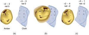
Charges in atoms and molecules can be separated—for example, by rubbing materials together. Some atoms and molecules have a greater affinity for electrons than others and will become negatively charged by close contact in rubbing, leaving the other material positively charged. (See Figure 9.8.) Positive charge can similarly be induced by rubbing. Methods other than rubbing can also separate charges. Batteries, for example, use combinations of substances that interact in such a way as to separate charges. Chemical interactions may transfer negative charge from one substance to the other, making one battery terminal negative and leaving the first one positive.
No charge is actually created or destroyed when charges are separated as we have been discussing. Rather, existing charges are moved about. In fact, in all situations the total amount of charge is always constant. This universally obeyed law of nature is called the law of conservation of charge, which states that total charge is constant in any process.
Making Connections: Conservation Laws
Only a limited number of physical quantities are universally conserved. Charge is one—energy, momentum, and angular momentum are others. Because they are conserved, these physical quantities are used to explain more phenomena and form more connections than other, less basic quantities. We find that conserved quantities give us great insight into the rules followed by nature and hints to the organization of nature. Discoveries of conservation laws have led to further discoveries, such as the weak nuclear force and the quark substructure of protons and other particles.
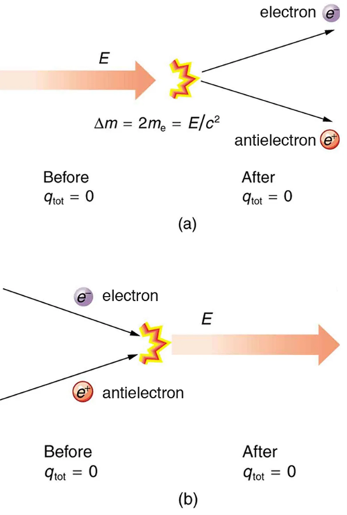
The law of conservation of charge is absolute—it has never been observed to be violated. Charge, then, is a special physical quantity, joining a very short list of other quantities in nature that are always conserved. Other conserved quantities include energy, momentum, and angular momentum.
Coulomb’s Law
Through the work of scientists in the late 18th century, the main features of the electrostatic force—the existence of two types of charge, the observation that like charges repel, unlike charges attract, and the decrease of force with distance—were eventually refined and expressed as a mathematical formula. The mathematical formula for the electrostatic force is called Coulomb’s law after the French physicist Charles Coulomb (1736–1806), who performed experiments and first proposed a formula to calculate it.
Although the law determining the magnitude of the Coulomb electric force has the same form as the law of gravity, the electric constant is 20 orders of magnitude greater than the gravitational constant. That is why electricity normally dominates gravity at the atomic and molecular level. Since there is only one type of mass but two opposite types of electric charge, gravity will dominate in large bodies unless there is a separation of charge.
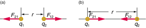
Coulomb’s law states that any two charged particles (q1,q2) — with charge measured in units of Coulombs — at a distance r from each other will experience a force of repulsion or attraction along the line joining them equal to:
F=k (q1 q2/r2)
Although the formula for Coulomb’s law is simple, it was no mean task to prove it. The experiments Coulomb did, with the primitive equipment then available, were difficult. Modern experiments have verified Coulomb’s law to great precision. For example, it has been shown that the force is inversely proportional to distance between two objects squared (F∝1/r2) to an accuracy of 1 part in 1016. No exceptions have ever been found, even at the small distances within the atom.
Electric Field and Electric Forces
Contact forces, such as between a baseball and a bat, are explained on the small scale by the interaction of the charges in atoms and molecules in close proximity. They interact through forces that include the Coulomb force. Action at a distance is a force between objects that are not close enough for their atoms to “touch.” That is, they are separated by more than a few atomic diameters.
For example, a charged rubber comb attracts neutral bits of paper from a distance via the Coulomb force. It is very useful to think of an object being surrounded in space by a force field. The force field carries the force to another object (called a test object) some distance away.
Electric Current and Electric Circuitry
Electric current is defined to be the rate at which charge flows. Voltage is the potential difference in energy between two points. It is this potential difference that drives electric current. We can think of various devices—such as batteries, generators, wall outlets, and so on—which are necessary to maintain a current. All such devices create a potential difference and are loosely referred to as voltage sources. When a voltage source is connected to a conductor, it applies a potential difference V that creates an electric field. The electric field in turn exerts force on charges, causing current.
Ohm’s Law
The current that flows through most substances is directly proportional to the voltage V applied to it. The German physicist Georg Simon Ohm (1787–1854) was the first to demonstrate experimentally that the current in a metal wire is directly proportional to the voltage applied:
I ∝ V
This important relationship is known as Ohm’s law. It can be viewed as a cause-and-effect relationship, with voltage the cause and current the effect.
Resistance and Simple Circuits
If voltage drives current, what impedes it? The electric property that impedes current (crudely similar to friction and air resistance) is called resistance (R). Collisions of moving charges with atoms and molecules in a substance transfer energy to the substance and limit current. Resistance is defined as inversely proportional to current, or
I ∝ (1/R)
Thus, for example, current is cut in half if resistance doubles. Combining the relationships of current to voltage and current to resistance gives
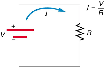
1 = (V/R)
This relationship is also called Ohm’s law. Ohm’s law in this form really defines resistance for certain materials. Ohm’s law (like Hooke’s law) is not universally valid. The many substances for which Ohm’s law holds are called ohmic. These include good conductors like copper and aluminum, and some poor conductors under certain circumstances. Ohmic materials have a resistance R that is independent of voltage V and current I. An object that has simple resistance is called a resistor, even if its resistance is small. The unit for resistance is an ohm and is given the symbol Ω (upper case Greek omega).
Figure 9.11 shows the schematic for a simple circuit. A simple circuit has a single voltage source and a single resistor. The wires connecting the voltage source to the resistor can be assumed to have negligible resistance, or their resistance can be included in R.
Resistors in Parallel and In Series
Most circuits have more than one component, called a resistor that limits the flow of charge in the circuit. A measure of this limit on charge flow is called resistance. The simplest combinations of resistors are the series and parallel connections illustrated in Figure 9.12. The total resistance of a combination of resistors depends on both their individual values and how they are connected.
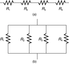
When are resistors in series? Resistors are in series whenever the flow of charge, called the current, must flow through devices sequentially. For example, if current flows through a person holding a screwdriver and into the Earth, then R1 in Figure 9.13(a) could be the resistance of the screwdriver’s shaft, R2 the resistance of its handle, R3 the person’s body resistance, and R4 the resistance of her shoes.
Figure 9.13 shows resistors in series connected to a voltage source. It seems reasonable that the total resistance is the sum of the individual resistances, considering that the current has to pass through each resistor in sequence. (This fact would be an advantage to a person wishing to avoid an electrical shock, who could reduce the current by wearing high-resistance rubber-soled shoes. It could be a disadvantage if one of the resistances were a faulty high-resistance cord to an appliance that would reduce the operating current.)
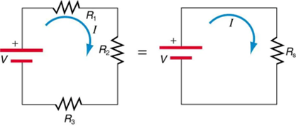
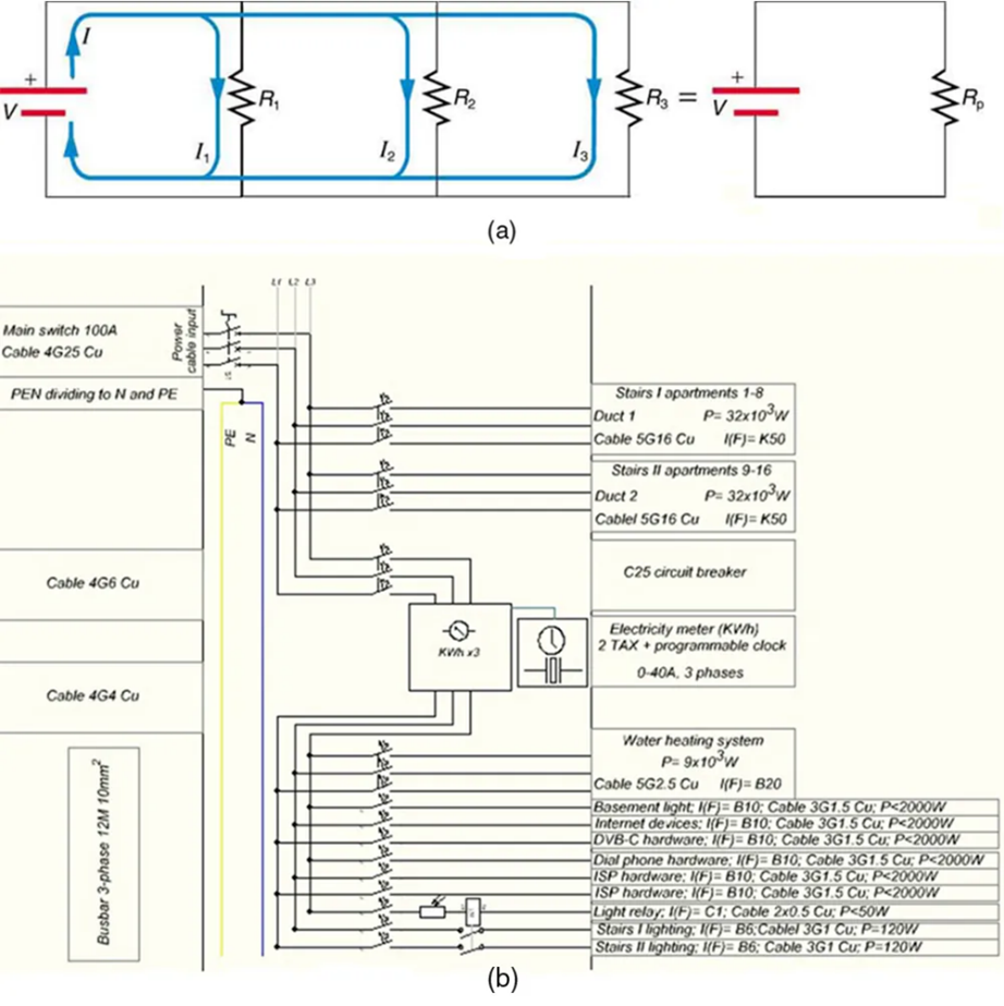
Figure 9.14 shows resistors in parallel, wired to a voltage source. Resistors are in parallel when each resistor is connected directly to the voltage source by connecting wires having negligible resistance. Each resistor thus has the full voltage of the source applied to it.
Each resistor draws the same current it would if it alone were connected to the voltage source (provided the voltage source is not overloaded). For example, an automobile’s headlights, radio, and so on, are wired in parallel, so that they utilize the full voltage of the source and can operate completely independently. The same is true in your house, or any building. (See Figure 9.14b.)
Direct Current and Alternating Current
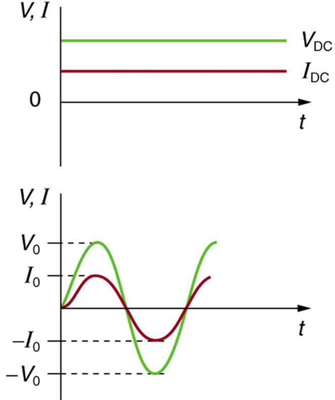
Most of the examples dealt with so far, and particularly those utilizing batteries, have constant voltage sources. Once the current is established, it is thus also a constant. Direct current (DC) is the flow of electric charge in only one direction. It is the steady state of a constant-voltage circuit. Most well-known applications, however, use a time-varying voltage source. Alternating current (AC) is the flow of electric charge that periodically reverses direction. If the source varies periodically, particularly sinusoidally, the circuit is known as an alternating current circuit. Examples include the commercial and residential power that serves so many of our needs. Fig 9.15 shows graphs of voltage and current versus time for typical DC and AC power. The AC voltages and frequencies commonly used in homes and businesses vary around the world.
Voltmeters and Ammeters
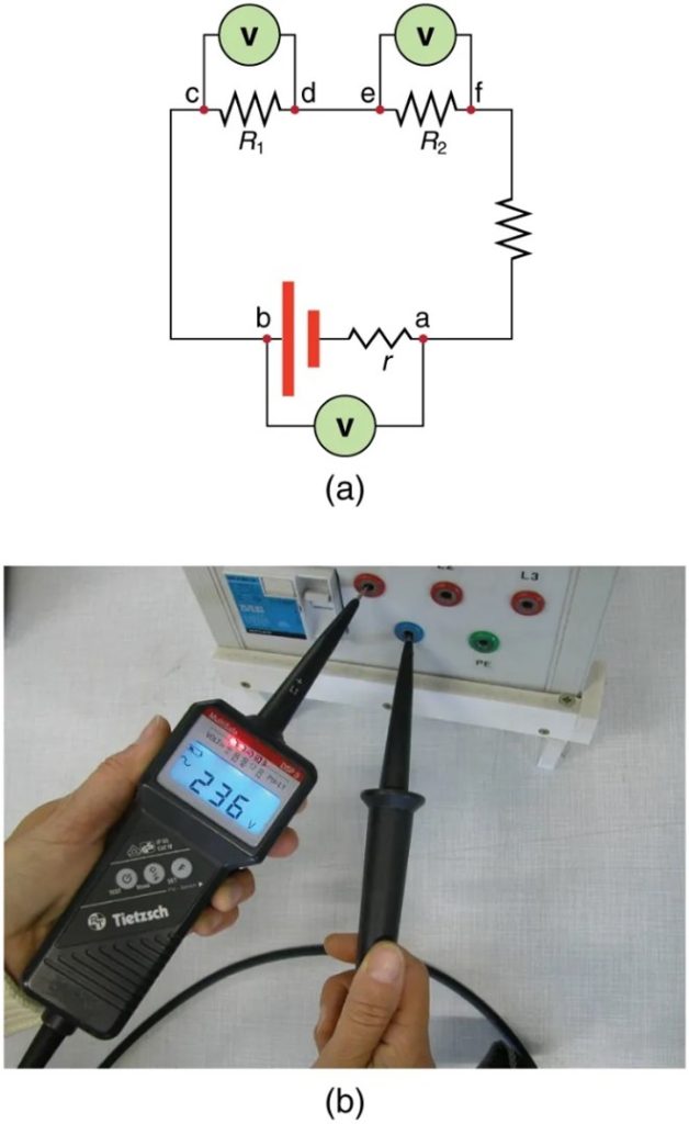
Voltmeters measure voltage, whereas ammeters measure current. Some of the meters in automobile dashboards, digital cameras, cell phones, and tuner-amplifiers are voltmeters or ammeters. (See Figure 9.16.) The internal construction of the simplest of these meters and how they are connected to the system they monitor give further insight into applications of series and parallel connections.

Voltmeters are connected in parallel with whatever device’s voltage is to be measured. A parallel connection is used because objects in parallel experience the same potential difference. (See Figure 9.17 where the voltmeter is represented by the symbol V.)
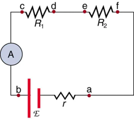
Ammeters are connected in series with whatever device’s current is to be measured. A series connection is used because objects in series have the same current passing through them. (See Figure 9.18, where the ammeter is represented by the symbol A.)
Check Your Understanding
The content in this chapter is adapted from multiple sources. The overall chapter structure is adapted from Exploring the Physical World and used under a Creative Commons Attribution-NonCommercial-ShareAlike 4.0 International License. The sections on introduction to electricity, static electricity, and charges, resistance and electrical circuits, direct and alternating current, and voltmeters and ammeters adapted from College Physics 2e by OpenStax and are used under a Creative Commons-Attribution 4.0 International License. Other content and interactive activities are the original work of the authors of this text and are shared under a Creative Commons-Attribution 4.0 International License.
Media Attributions
- Fig. 9.1 © Ken Bosma is licensed under a CC0 (Creative Commons Zero) license
- Fig. 9.2 © OpenStax is licensed under a CC BY (Attribution) license
- Fig. 9.3 © Sebakoamber is licensed under a Public Domain license
- Fig. 9.4 © OpenStax is licensed under a CC BY (Attribution) license
- Fig. 9.5 © OpenStax is licensed under a CC BY (Attribution) license
- Fig. 9.6 © OpenStax is licensed under a CC BY (Attribution) license
- Fig. 9.7 © OpenStax is licensed under a CC BY (Attribution) license
- Fig. 9.8 © OpenStax is licensed under a CC BY (Attribution) license
- Fig. 9.9 © OpenStax is licensed under a CC BY (Attribution) license
- Fig. 9.10 © OpenStax is licensed under a CC BY (Attribution) license
- Fig. 9.11 © OpenStax is licensed under a CC BY (Attribution) license
- Fig. 9.12 © OpenStax is licensed under a CC BY (Attribution) license
- Fig. 9.13 © OpenStax is licensed under a CC BY (Attribution) license
- Fig. 9.14 © OpenStax is licensed under a CC BY (Attribution) license
- Fig. 9.15 © OpenStax is licensed under a CC BY (Attribution) license
- Fig. 9.16 © Christian Giersing is licensed under a Public Domain license
- Fig. 9.17 © OpenStax is licensed under a CC BY (Attribution) license
- Fig. 9.18 © OpenStax is licensed under a CC BY (Attribution) license
a buildup of electric charge on the surface of an object
table of the chemical elements arranged in order of atomic number, usually in rows, so that elements with similar atomic structure (and hence similar chemical properties) appear in vertical columns
qualities and characteristics of individual substances that describe and identify them
anything that takes up space and can be weighed
one of the four fundamental forces of nature; the electromagnetic force consists of static electricity, moving electricity and magnetism
phenomenon associated with magnetic fields, which arise from the motion of electric charges
a physical property of an object that causes it to be attracted toward or repelled from another charged object; each charged object generates and is influenced by a force called an electromagnetic force
negatively charged sub-atomic particles; together with protons and neutrons they compose all atoms
positively charged particles that, together with the electrically neutral particles called neutrons, make up the nucleus of an atom
smallest particle of an element that has the properties of that element and can enter into a chemical combination
two or more atoms joined by strong forces called chemical bonds
total charge is constant in any process
amount and direction of attraction or repulsion between two charged bodies
mathematical equation calculating the electrostatic force vector between two charged particles
another term for the electrostatic force
region in which a test particle will experience a force
rate at which charge flows
electrical potential energy per unit charge; electric pressure created by a power source, such as a battery
region around a charged particle or object within which a force would be exerted on other charged particles or objects
an empirical relation stating that the current I is proportional to the potential difference V, ∝ V; it is often written as I = V/R, where R is the resistance
electric property that impedes current
object that has simple resistance
closed loop through which charges can continuously move
flow of electric charge in only one direction
flow of electric charge that periodically reverses direction
instrument for measuring electric potential in volts
instrument for measuring electric current in amperes
