5 Waves, Electromagnetic Radiation, and Sound
Chapter Learning Objectives
After successful completion of the assignments in this section, you will be able to demonstrate competency in the following areas:
- Recognize that waves carry energy, but not matter (CLO1)
- Define mechanical waves (CLO1)
- Distinguish between transverse waves and compressional waves (CLO1)
- Compare and contrast transverse and compressional waves (CLO3)
- Describe the relationship between frequency and wavelength (CLO3)
- Explain how a wave's amplitude is related to the wave's energy (CLO3)
- Calculate the speed of a wave (CLO5)
- Identify what influences the speed of sound (CLO3)
- Discuss and apply various properties of sound (CLO3)
- Identify the properties of electromagnetic radiation (CLO3)

Introduction to Waves
What do we mean when we say something is a wave? The most intuitive and easiest wave to imagine is the familiar water wave. More precisely, a wave is a disturbance that propagates, or moves from the place it was created. For water waves, the disturbance is on the surface of the water, perhaps created by a rock thrown into a pond or by a swimmer splashing the surface repeatedly. For sound waves, the disturbance is a change in air pressure, perhaps created by the oscillating cone inside a speaker. For earthquakes, there are several types of disturbances, including the disturbance of Earth’s surface and pressure disturbances under the surface. Even radio waves are most easily understood using an analogy with water waves. Visualizing water waves is useful because there is more to it than just a mental image. Water waves exhibit characteristics common to all waves, such as amplitude, period, frequency, and energy. All wave characteristics can be described by a small set of underlying principles.
Misconception Alert
Many people think that water waves push water from one direction to another. In fact, the particles of water tend to stay in one location, save for moving up and down due to the energy in the wave. The energy moves forward through the water, but the water stays in one place. If you feel yourself pushed in an ocean, what you feel is the energy of the wave, not a rush of water.
Wave Characteristics
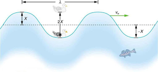
The simplest waves repeat themselves for several cycles and are associated with simple harmonic motion. Let us start by considering the simplified water wave in Figure 5.2. The wave is an up and down disturbance of the water surface. It causes a seagull to move up and down in simple harmonic motion as the wave crests and troughs (peaks and valleys) pass under the bird. The time for one complete up and down motion is the wave’s period T.
The wave’s frequency is f = 1/T. The wave itself moves to the right in the figure. This movement of the wave is actually the disturbance moving to the right, not the water itself (or the bird would move to the right). We define wave velocity vw to be the speed at which the disturbance moves. Wave velocity is sometimes also called the propagation velocity or propagation speed, because the disturbance propagates from one location to another.
Take-Home Experiment: Waves in a Bowl
Fill a large bowl or basin with water and wait for the water to settle so there are no ripples. Gently drop a cork into the middle of the bowl. Estimate the wavelength and period of oscillation of the water wave that propagates away from the cork. Remove the cork from the bowl and wait for the water to settle again. Gently drop the cork at a height that is different from the first drop. Does the wavelength depend upon how high above the water the cork is dropped?
Example 5.1
CALCULATE THE VELOCITY OF WAVE PROPAGATION: GULL IN THE OCEAN
Calculate the wave velocity of the ocean wave in Figure 5.2 if the distance between wave crests is 10.0 m and the time for a seagull to bob up and down is 5.00 s.
Strategy
We are asked to find vw. The given information tells us that λ = 10.0 m and T = 5.00 s. Therefore, we can use vw = λ/T to find the wave velocity.
Solution
- Enter the known values into vw = λ/T
vw = 10.0 m/5.00 s = 2.00 m
Discussion
This slow speed seems reasonable for an ocean wave. Note that the wave moves to the right in the figure at this speed, not the varying speed at which the seagull moves up and down.
Electromagnetic Spectrum
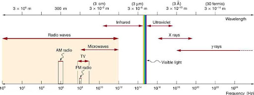
The electromagnetic spectrum shows the major categories of electromagnetic waves. The range of frequencies and wavelengths is remarkable. The dividing line between some categories is distinct, whereas other categories overlap.
Figure 5.3 shows how the various types of electromagnetic waves are categorized according to their wavelengths and frequencies—that is, it shows the electromagnetic spectrum. Many of the characteristics of the various types of electromagnetic waves are related to their frequencies and wavelengths, as we shall see. We can get a good understanding of electromagnetic waves by considering how they are produced. Whenever a current varies, associated electric fields and magnetic fields vary, moving out from the source like waves.
Electromagnetic Spectrum: Rules of Thumb
Three rules that apply to electromagnetic waves in general are the following:
- High-frequency electromagnetic waves are more energetic and are more able to penetrate than low-frequency waves.
- High-frequency electromagnetic waves can carry more information per unit time than low-frequency waves.
- The shorter the wavelength of any electromagnetic wave probing a material, the smaller the detail it is possible to resolve.
Note that there are exceptions to these rules of thumb.
Transmission, Reflection, and Absorption
What happens when an electromagnetic wave impinges on a material? If the material is transparent to the particular frequency, then the wave can largely be transmitted. If the material is opaque to the frequency, then the wave can be totally reflected. The wave can also be absorbed by the material, indicating that there is some interaction between the wave and the material, such as the thermal agitation of molecules.
Of course it is possible to have partial transmission, reflection, and absorption. We normally associate these properties with visible light, but they do apply to all electromagnetic waves. What is not obvious is that something that is transparent to light may be opaque at other frequencies. For example, ordinary glass is transparent to visible light but largely opaque to ultraviolet radiation. Human skin is opaque to visible light—we cannot see through people—but transparent to X-rays.
Radio and TV Waves
The broad category of radio waves is defined to contain any electromagnetic wave produced by currents in wires and circuits. Its name derives from their most common use as a carrier of audio information (i.e., radio). The name is applied to electromagnetic waves of similar frequencies regardless of source. Radio waves from outer space, for example, do not come from alien radio stations. They are created by many astronomical phenomena, and their study has revealed much about nature on the largest scales.
There are many uses for radio waves, and so the category is divided into many subcategories, including microwaves and those electromagnetic waves used for AM and FM radio, cellular telephones, and TV.
The lowest commonly encountered radio frequencies are produced by high-voltage AC power transmission lines at frequencies of 50 or 60 Hz. (See Figure 5.4.) These extremely long wavelength electromagnetic waves (about 6000 km!) are one means of energy loss in long-distance power transmission.
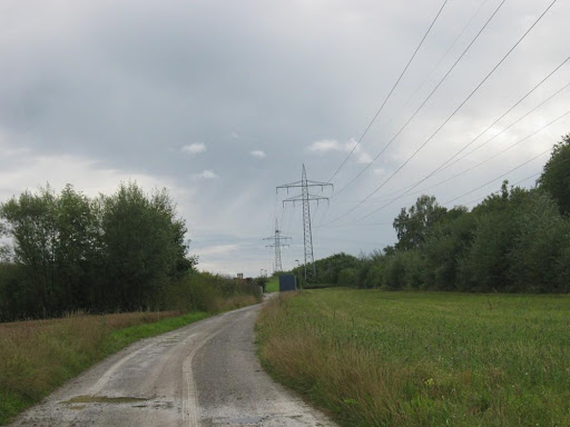
There is an ongoing controversy regarding potential health hazards associated with exposure to these electromagnetic fields. Some people suspect that living near such transmission lines may cause a variety of illnesses, including cancer. But demographic data are either inconclusive or simply do not support the hazard theory. Recent reports that have looked at many European and American epidemiological studies have found no increase in risk for cancer due to exposure to electromagnetic fields.
Rays
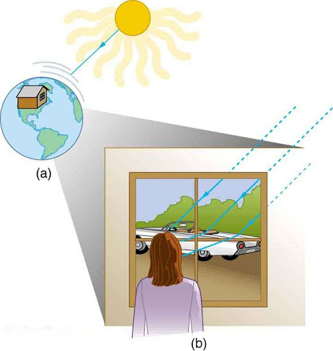
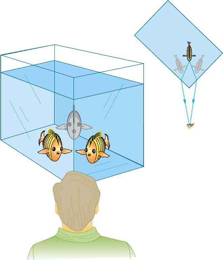
There are three ways in which light can travel from a source to another location. (See Figure 5.5.) It can come directly from the source through empty space, such as from the Sun to Earth. Or light can travel through various media, such as air and glass, to the person. Light can also arrive after being reflected, such as by a mirror. In all of these cases, light is modeled as traveling in straight lines called rays. Light may change direction when it encounters objects (such as a mirror) or in passing from one material to another (such as in passing from air to glass), but it then continues in a straight line or as a ray. It is acceptable to visualize light rays as laser rays (or even science fiction depictions of ray guns).
The word “ray” comes from mathematics and here means a straight line that originates at some point.
Experiments, as well as our own experiences, show that when light interacts with objects several times as large as its wavelength, it travels in straight lines and acts like a ray. Its wave characteristics are not pronounced in such situations. Since the wavelength of light is less than a micron (a thousandth of a millimeter), it acts like a ray in the many common situations in which it encounters objects larger than a micron. For example, when light encounters anything we can observe with unaided eyes, such as a mirror, it acts like a ray, with only subtle wave characteristics. We will concentrate on the ray characteristics.
Since light moves in straight lines, changing directions when it interacts with materials, it is described by geometry and simple trigonometry. This part of optics, where the ray aspect of light dominates, is therefore called geometric optics. There are two laws that govern how light changes direction when it interacts with matter. These are the law of reflection, for situations in which light bounces off matter, and the law of refraction, for situations in which light passes through matter.
Geometric Optics
The part of optics dealing with the ray aspect of light is called geometric optics.
Whenever we look into a mirror, or squint at sunlight glinting from a lake, we are seeing a reflection. When you look at a book's page, too, you are seeing light reflected from it. Large telescopes use reflection to form an image of stars and other astronomical objects.
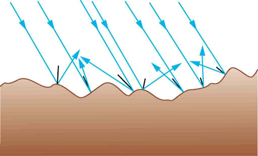
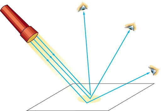
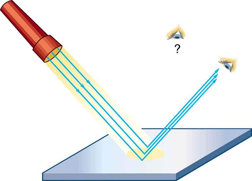
The law of reflection is illustrated in Figure 5.6, which also shows how the angles are measured relative to the perpendicular to the surface at the point where the light ray strikes. We expect to see reflections from smooth surfaces, but Figure 5.7 illustrates how a rough surface reflects light. Since the light strikes different parts of the surface at different angles, it is reflected in many different directions, or diffused. Diffused light is what allows us to see a sheet of paper from any angle, as illustrated in Figure 5.8. Many objects, such as people, clothing, leaves, and walls, have rough surfaces and can be seen from all sides. A mirror, on the other hand, has a smooth surface (compared with the wavelength of light) and reflects light at specific angles, as illustrated in Figure 5.9. When the moon reflects from a lake, as shown in Figure 5.10, a combination of these effects takes place.
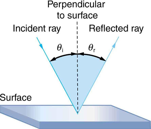

The law of reflection is very simple: The angle of reflection (θr) equals the angle of incidence (θi).
Refraction
The changing of a light ray’s direction (loosely called bending) when it passes through variations in matter is called refraction. Refraction is responsible for a tremendous range of optical phenomena, from the action of lenses to voice transmission through optical fibers.
Speed of Light
The speed of light (c) not only affects refraction; it is one of the central concepts of Einstein’s theory of relativity. As the accuracy of the measurements of the speed of light were improved, c was found not to depend on the velocity of the source or the observer. However, the speed of light does vary in a precise manner with the material it traverses. Early attempts to measure the speed of light, such as those made by Galileo, determined that light moves extremely fast, perhaps instantaneously. The first real evidence that light traveled at a finite speed came from the Danish astronomer Ole Roemer in the late 17th century.
The speed of light is now known to great precision. In fact, the speed of light in a vacuum
is so important that it is accepted as one of the basic physical quantities and has the fixed value
Take-Home Experiment: Bending Light
Lenses
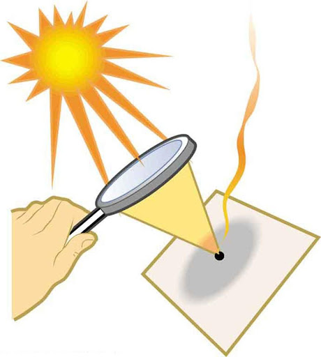
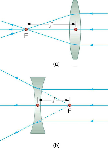
The greater effect a lens has on light rays, the more powerful it is said to be. For example, a powerful converging lens will focus parallel light rays closer to itself and will have a smaller focal length than a weak lens. The light will also focus into a smaller and more intense spot for a more powerful lens.
A lens that causes the light rays to bend away from its axis is called a diverging lens. The concave lens is a diverging lens, because it causes the light rays to bend away (diverge) from its axis.
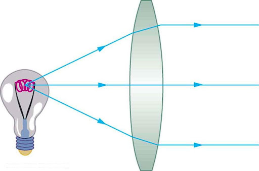
As noted in the initial discussion of the law of refraction, the paths of light rays are exactly reversible. This means that the direction of the arrows could be reversed for all of the rays in Figure 5.12. For example, if a point light source is placed at the focal point of a convex lens, as shown in Figure 5.14, parallel light rays emerge from the other side.
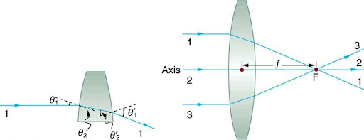
Ray Tracing and Thin Lenses
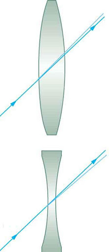
Ray tracing is the technique of determining or following (tracing) the paths that light rays take. For rays passing through matter, the law of refraction is used to trace the paths. Here we use ray tracing to help us understand the action of lenses in situations ranging from forming images on film to magnifying small print to correcting nearsightedness. While ray tracing for complicated lenses, such as those found in sophisticated cameras, may require computer techniques, there is a set of simple rules for tracing rays through thin lenses. A thin lens is defined to be one whose thickness allows rays to refract, as illustrated in Figure 5.12, but does not allow properties such as dispersion and aberrations. An ideal thin lens has two refracting surfaces but the lens is thin enough to assume that light rays bend only once. A thin symmetrical lens has two focal points, one on either side and both at the same distance from the lens. (See Figure 5.15.) Another important characteristic of a thin lens is that light rays through its center are deflected by a negligible amount, as seen in Figure 5.16.
Rules for Ray Tracing
A ray entering a converging lens parallel to its axis passes through the focal point F of the lens on the other side.
A ray entering a diverging lens parallel to its axis seems to come from the focal point F.
A ray passing through the center of either a converging or a diverging lens does not change direction.
A ray entering a converging lens through its focal point exits parallel to its axis.
A ray that enters a diverging lens by heading toward the focal point on the opposite side exits parallel to the axis.
Using paper, pencil, and a straight edge, ray tracing can accurately describe the operation of a lens. The rules for ray tracing for thin lenses are based on the preceding illustrations.
Image Formation by Thin Lenses
In some circumstances, a lens forms an obvious image, such as when a movie projector casts an image onto a screen. In other cases, the image is less obvious. Where, for example, is the image formed by eyeglasses? We will use ray tracing for thin lenses to illustrate how they form images, and we will develop equations to describe the image formation quantitatively.
Consider an object some distance away from a converging lens, as shown in Figure 5.17. To find the location and size of the image formed, we trace the paths of selected light rays originating from one point on the object, in this case the top of the person’s head. The figure shows three rays from the top of the object that can be traced using the ray tracing rules given above. (Rays leave this point going in many directions, but we concentrate on only a few with paths that are easy to trace.) The first ray is one that enters the lens parallel to its axis and passes through the focal point on the other side (rule 1). The second ray passes through the center of the lens without changing direction (rule 3). The third ray passes through the nearer focal point on its way into the lens and leaves the lens parallel to its axis (rule 4). The three rays cross at the same point on the other side of the lens. The image of the top of the person’s head is located at this point. All rays that come from the same point on the top of the person’s head are refracted in such a way as to cross at the point shown. Rays from another point on the object, such as her belt buckle, will also cross at another common point, forming a complete image, as shown. Although three rays are traced in Figure 5.17, only two are necessary to locate the image. It is best to trace rays for which there are simple ray tracing rules. Before applying ray tracing to other situations, let us consider the example shown in Figure 5.17 in more detail.
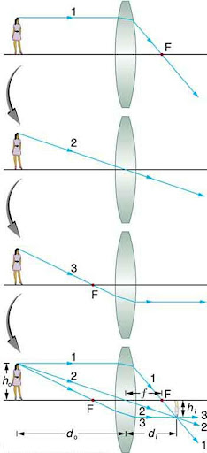
The image formed in Figure 5.17 is a real image, meaning that it can be projected. That is, light rays from one point on the object actually cross at the location of the image and can be projected onto a screen, a piece of film, or the retina of an eye, for example. Figure 5.18 shows how such an image would be projected onto film by a camera lens. This figure also shows how a real image is projected onto the retina by the lens of an eye. Note that the image is there whether it is projected onto a screen or not.
Take-Home Experiment: A Visit to the Optician
Real Image
The image in which light rays from one point on the object actually cross at the location of the image and can be projected onto a screen, a piece of film, or the retina of an eye is called a real image.
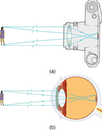
Real images are formed by converging lenses whenever an object is farther from the lens than its focal length. This is true for movie projectors, cameras, and the eye.
A different type of image is formed when an object, such as a person's face, is held close to a convex lens. The image is upright and larger than the object, as seen in Figure 5.19(b), and so the lens is called a magnifier. If you slowly pull the magnifier away from the face, you will see that the magnification steadily increases until the image begins to blur. Pulling the magnifier even farther away produces an inverted image as seen in Figure 5.19(a). The distance at which the image blurs, and beyond which it inverts, is the focal length of the lens. To use a convex lens as a magnifier, the object must be closer to the converging lens than its focal length.
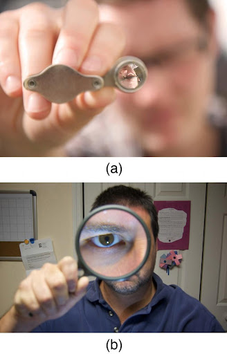
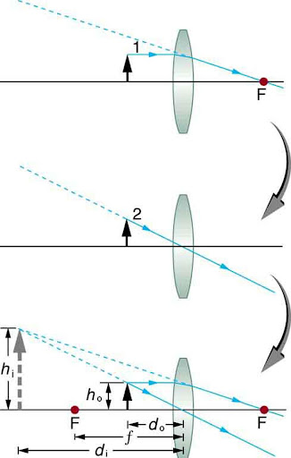
Figure 5.20 uses ray tracing to show how an image is formed when an object is held closer to a converging lens than its focal length. Rays coming from a common point on the object continue to diverge after passing through the lens, but all appear to originate from a point at the location of the image. The image is on the same side of the lens as the object and is farther away from the lens than the object. This image, like all case 2 images, cannot be projected and, hence, is called a virtual image. Light rays only appear to originate at a virtual image; they do not actually pass through that location in space. A screen placed at the location of a virtual image will receive only diffuse light from the object, not focused rays from the lens. Additionally, a screen placed on the opposite side of the lens will receive rays that are still diverging, and so no image will be projected on it. We can see the magnified image with our eyes, because the lens of the eye converges the rays into a real image projected on our retina. Finally, we note that a virtual image is upright and larger than the object, meaning that the magnification is positive and greater than 1.
Virtual Image
An image that is on the same side of the lens as the object and cannot be projected on a screen is called a virtual image.
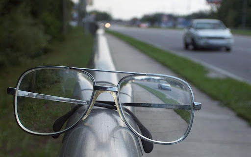
A third type of image is formed by a diverging or concave lens. Try looking through eyeglasses meant to correct nearsightedness. (See Figure 5.21.) You will see an image that is upright but smaller than the object. This means that the magnification is positive but less than 1.
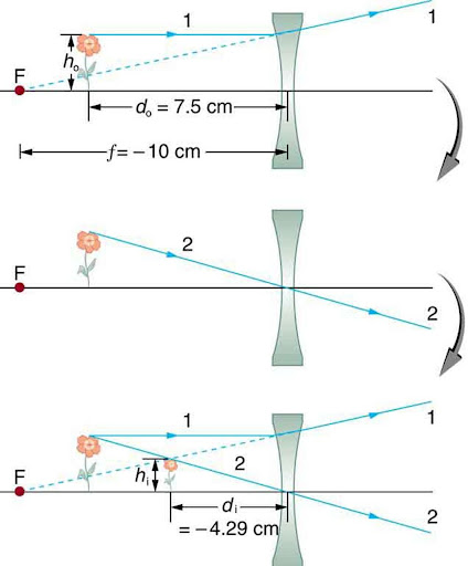
The ray diagram in Figure 5.22 shows that the image is on the same side of the lens as the object and, hence, cannot be projected—it is a virtual image. Note that the image is closer to the lens than the object. This is a case 3 image, formed for any object by a negative focal length or diverging lens.
Sound
Sound can be used as a familiar illustration of waves. Because hearing is one of our most important senses, it is interesting to see how the physical properties of sound correspond to our perceptions of it. Hearing is the perception of sound, just as vision is the perception of visible light. But sound has important applications beyond hearing. Ultrasound, for example, is not heard but can be employed to form medical images and is also used in treatment.
The physical phenomenon of sound is defined to be a disturbance of matter that is transmitted from its source outward. Sound is a wave. On the atomic scale, it is a disturbance of atoms that is far more ordered than their thermal motions. In many instances, sound is a periodic wave, and the atoms undergo simple harmonic motion.
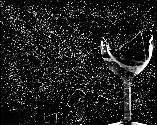
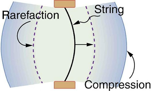
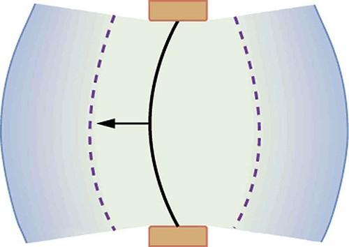
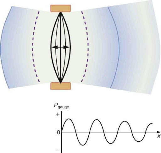
A vibrating string produces a sound wave as illustrated in Figure 5.24, Figure 5.25, and Figure 5.26. As the string oscillates back and forth, it transfers energy to the air, mostly as thermal energy created by turbulence. But a small part of the string’s energy goes into compressing and expanding the surrounding air, creating slightly higher and lower local pressures. These compressions (high pressure regions) and rarefactions (low pressure regions) move out as longitudinal pressure waves having the same frequency as the string—they are the disturbance that is a sound wave. (Sound waves in air and most fluids are longitudinal, because fluids have almost no shear strength. In solids, sound waves can be both transverse and longitudinal.) Figure 5.26 shows a graph of gauge pressure versus distance from the vibrating string.
Check Your Understanding
The content in this chapter is adapted from multiple sources. The overall chapter structure is adapted from Exploring the Physical World and used under a Creative Commons Attribution-NonCommercial-ShareAlike 4.0 International License. The sections on wave characteristics, geometric optics, lenses, and sound are adapted from College Physics 2e by OpenStax and are used under a Creative Commons-Attribution 4.0 International License. Other content and interactive activities are the original work of the authors of this text and are shared under a Creative Commons-Attribution 4.0 International License.
Media Attributions
- Figure 5.1 © Steve Jurvetson is licensed under a CC BY (Attribution) license
- Figure 5.2 © OpenStax is licensed under a CC BY (Attribution) license
- Figure 5.3 © OpenStax is licensed under a CC BY (Attribution) license
- Figure 5.4 © Zonk43 is licensed under a Public Domain license
- Figure 5.5 © OpenStax is licensed under a CC BY (Attribution) license
- Figure 5.6 © OpenStax is licensed under a CC BY (Attribution) license
- Figure 5.7 © OpenStax is licensed under a CC BY (Attribution) license
- Figure 5.8 © OpenStax is licensed under a CC BY (Attribution) license
- Figure 5.9 © OpenStax is licensed under a CC BY (Attribution) license
- Figure 5.10 © Diego Torres Silvestre is licensed under a CC BY (Attribution) license
- Figure 5.11 © OpenStax is licensed under a CC BY (Attribution) license
- Figure 5.12 © OpenStax is licensed under a CC BY (Attribution) license
- Figure 5.13 © OpenStax is licensed under a CC BY (Attribution) license
- figure 5.14 © OpenStax is licensed under a CC BY (Attribution) license
- Figure 5.15 © OpenStax is licensed under a CC BY (Attribution) license
- Figure 5.16 © OpenStax is licensed under a CC BY (Attribution) license
- Figure 5.17 © OpenStax is licensed under a CC BY (Attribution) license
- Figure 5.18 © OpenStax is licensed under a CC BY (Attribution) license
- Figure 5.19 © OpenStax is licensed under a CC BY (Attribution) license
- Figure 5.20 © OpenStax is licensed under a CC BY (Attribution) license
- Figure 5.21 © OpenStax is licensed under a CC BY (Attribution) license
- Figure 5.22 © OpenStax is licensed under a CC BY (Attribution) license
- Figure 5.23 © ||read|| is licensed under a CC BY (Attribution) license
- Figure 5.24 © OpenStax is licensed under a CC BY (Attribution) license
- Figure 5.25 © OpenStax is licensed under a CC BY (Attribution) license
- Figure 5.26 © OpenStax is licensed under a CC BY (Attribution) license
disturbance in which energy is transferred from one location to another
pattern of disturbance caused by the movement of energy traveling through a medium (such as air, water or any other liquid or solid matter) as it propagates away from the source of the sound
distance between the resting position and the maximum displacement of the wave
time it takes for two successive crests (one wavelength) to pass a specified point. The time it takes the wave to complete one full oscillation
number of waves that pass a fixed point in unit time
capacity of a physical system to perform work
repetitive movement back and forth through an equilibrium, or central, position, so that the maximum displacement on one side of this position is equal to the maximum displacement on the other side
point on the medium (wave) that exhibits the maximum amount of positive or upward displacement from the rest position
point on the medium (wave) that exhibits the maximum amount of negative or downward displacement from the rest position
distance traversed by a periodic, or cyclic, motion per unit time (in any direction)
range of wavelengths or frequencies over which electromagnetic radiation extends
form of radiation that travels through the universe; they are created because of vibrations between an electric field and a magnetic field
length of a wave from one peak to the next; measured from peak to trough
region around a charged particle or object within which a force would be exerted on other charged particles or objects
region around a magnetic material or a moving electric charge within which the force of magnetism acts
substance allowing light to pass through without appreciable scattering of light
substance allowing no light to pass through
passage of electromagnetic radiation through a medium
change in direction of a wave front at an interface between two different media so that the wave front returns into the medium from which it originated
transfer of the energy of a wave to matter as the wave passes through it
a beam of light or radiation
angle of reflection equals the angle of incidence; θr = θi
change in direction of a wave passing from one medium to another caused by its change in speed
angle between reflected ray and the normal at the point of incidence to a reflecting surface
angle formed between the normal and the incident ray at the point of incidence
light ray always deviates more toward the normal in the optically denser medium
lens shaped so that all light rays that enter it parallel to its axis cross one another at a single point on the opposite side of the lens
value calculated from the ratio of the speed of light in a vacuum to that in a second medium of greater density
point at which all radiation coming from a single direction and passing through a lens or striking a mirror converges, also called focus
distance from a lens or mirror to the focal point (F)
lens that focuses the light rays to a specific point called the focal point
lens that causes a beam of parallel rays to diverge after refraction, as from a virtual image; a lens that has a negative focal length
lens whose thickness allows rays to refract but does not allow properties such as dispersion and aberrations
image in which light rays from one point on the object actually cross at the location of the image and can be projected onto a screen, a piece of film, or the retina of an eye
image that is on the same side of the lens as the object and cannot be projected on a screen
